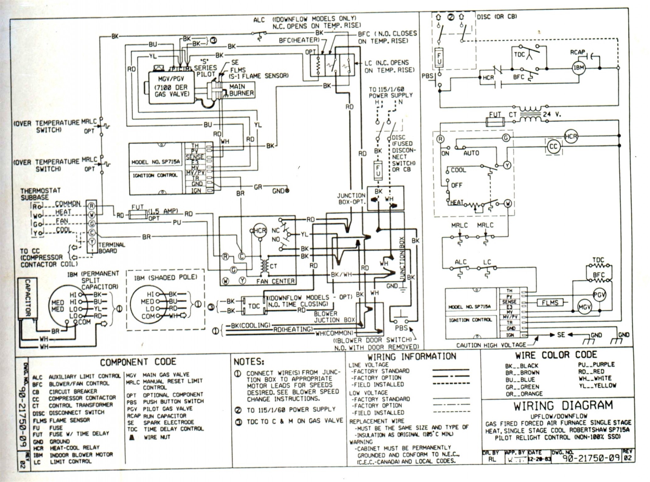
Oil Burner Wiring Diagram Wiring Diagram and Schematics
Beckett model SM OIL BURNER burner, furnace genuine parts
Replacement Parts Diagram. Thank you for purchasing a Beckett burner for use with your heating appliance. Please pay attention to the Safety Warnings contained within this instruc-tion manual. READ THIS MANUAL AND SAVE FOR YOUR RECORDS. Provide it to your qualifi ed service
BECKETT BURNER Parts Model AFG50MD Sears PartsDirect
Beckett AFG Oil Burner Instruction Manual Oil burner 1 Table Of Contents 2 3 4 5 6 7 8 9 10 11 12 page of 12 Table of Contents Bookmarks Advertisement Quick Links x Download this manual 8 Wire Burner 10 Startup Burner/Set Combustion 10 Perform Annual Maintenance 10 Startup & Adjust Burner 11 Replacement Parts MODEL

Beckett Afg Oil Burner Parts Diagram
Electronic Igniters With Baseplate Higher output voltage for better ignition, especially with cold oil Includes baseplate with terminals, gaskets and mounting hardware Adapts to multiple baseplates, even other vendors
Replacement Parts for CG4 Gas Burner Beckett Corporation
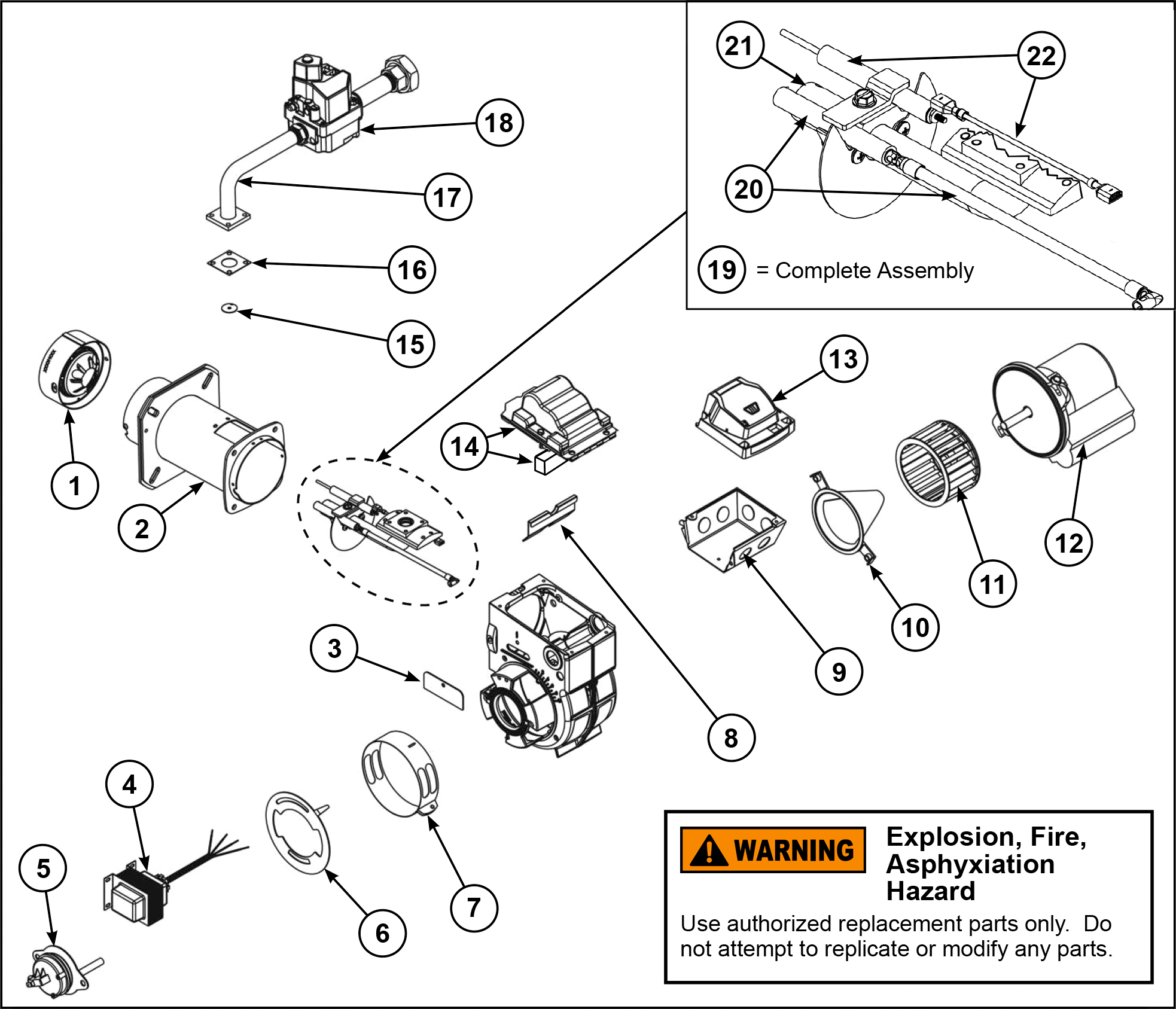
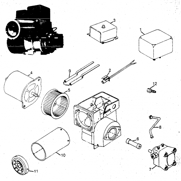
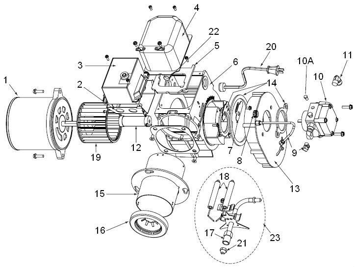
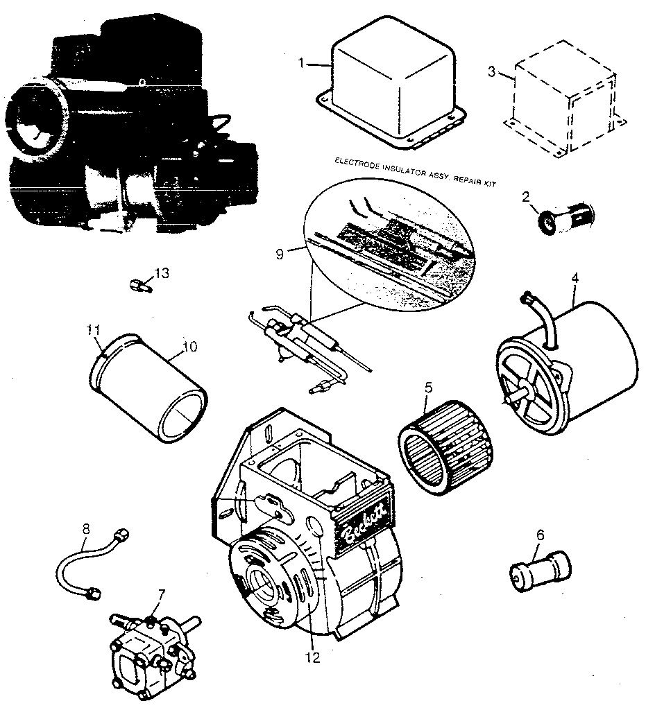
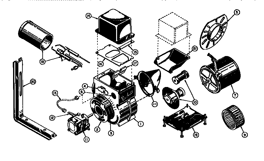
Page 15: Replacement Parts Diagram Cover, Burner Mounting Plate, Burner Cover Specify Thumbscrews, Cover mounting Specify * For retention head assemblies that do NOT have a sight- 51811U ing hole, contact Beckett's customer service for appropri- 32058U ate part number. SK967101 Part No. 51771U 51942U. Page 16: Beckett Limited Warranty.
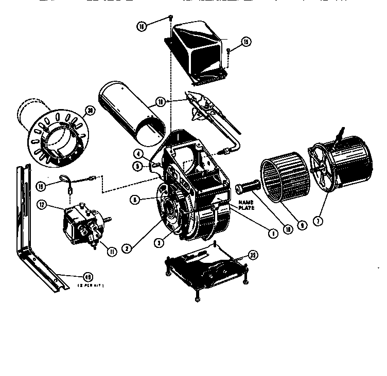
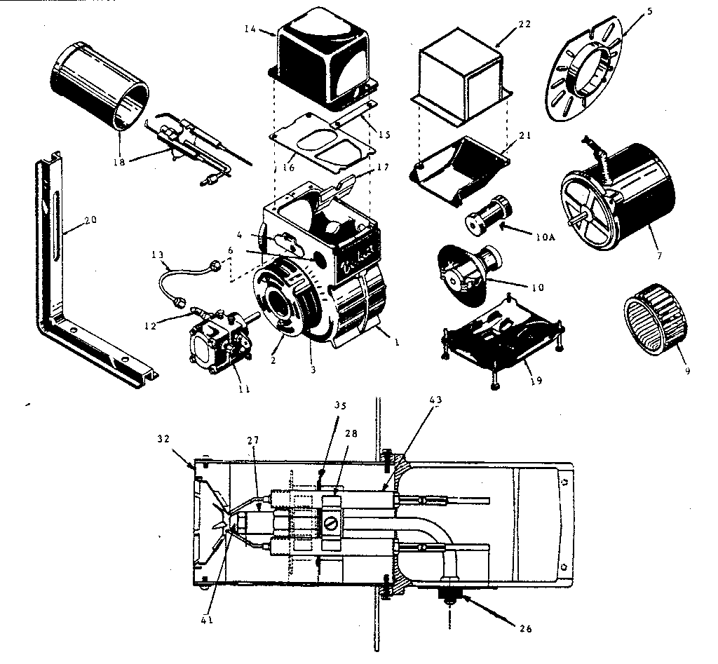
Beckett model AFII85 burner, furnace genuine parts
Unit parts diagram End cone Part # 59-19206-86 $ 35.76 In Stock Qty Add to cart # 8 Unit parts diagram Conn tube as Part # 59-19206-18 $ 9.06 In Stock
Oil Burner Wiring Diagram Wiring Diagram and Schematics
Parts Diagram Beckett Limited Warranty Information This manual contains information that applies to both AF and AFG burners. These burners may appear to be basically identical, but there are differences in design and performance. Please review the comparison chart below:. Page 3: General Information Do NOT remove the air guide from the AFG.
Beckett Burner Wiring Diagram
Sat. 7:00 am-9:00 pm. Central. Sun. 8:00 am-8:00 pm. Central. Beckett AFG OIL BURNER furnace parts - manufacturer-approved parts for a proper fit every time! We also have installation guides, diagrams and manuals to help you along the way!
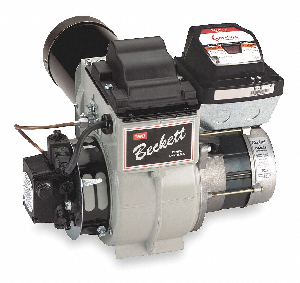
RW BECKETT, B2503, Complete Flame Retention, Hot Water and Steam Boiler
Beckett Burners & Parts. Miscellaneous Parts. Miscellaneous Parts. 125. Transformer Gasket Kit For Beckett A, AF, and AFG Series Oil Burners. SKU:.
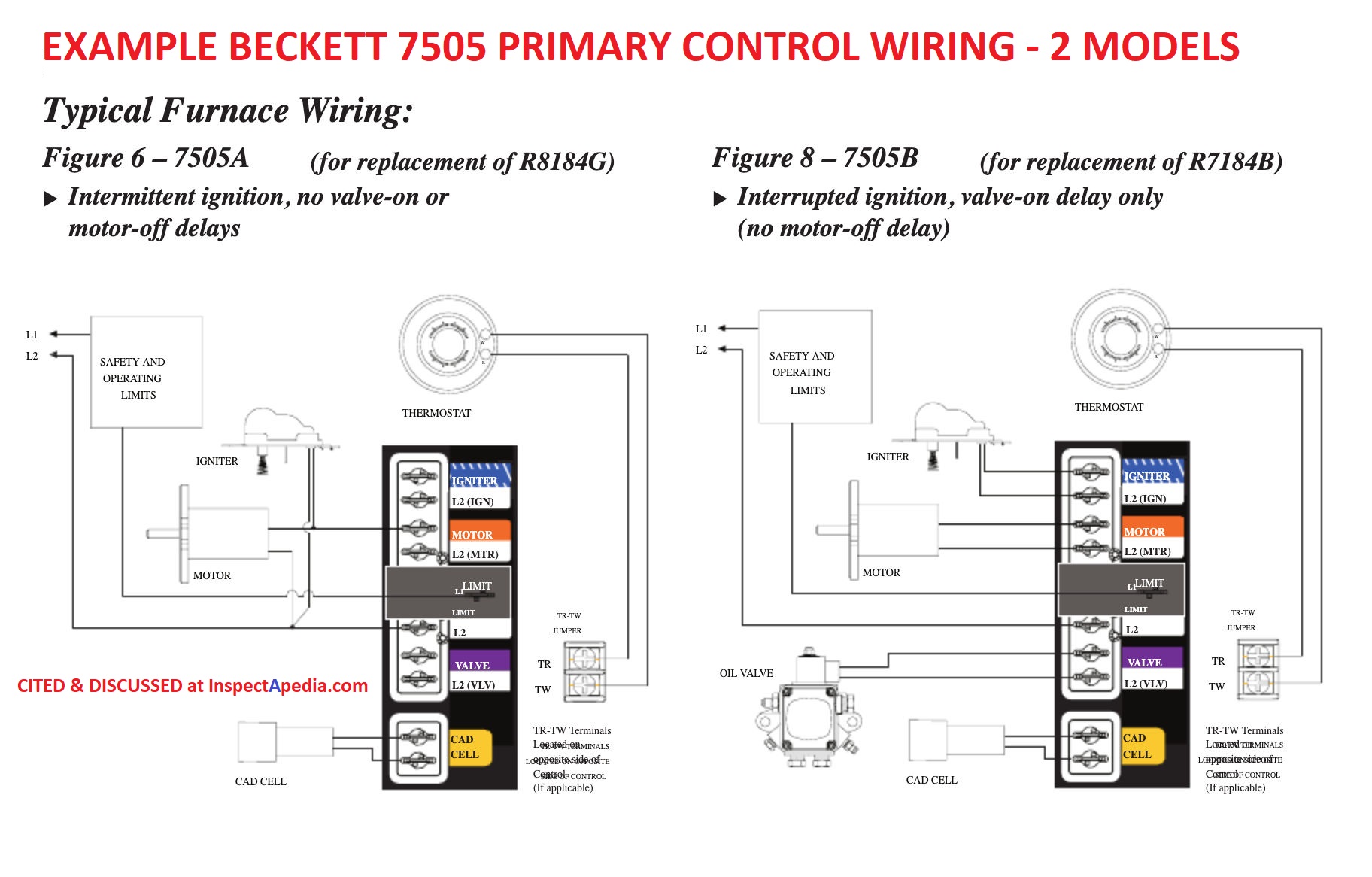
Wiring A Beckett Oil Burner
Parts diagram Connector tube assembly (suntec or webster) Part # 5-636 The manufacturer no longer makes this part, and there's no substitute part # 11B Parts diagram Fuel unit, webster (two stage) Part # 2-554 The manufacturer no longer makes this part, and there's no substitute part # 12 Parts diagram Pump outlet elbow
Beckett Oil Furnace Parts
DC Burners ADC, SDC Contact your Beckett representative for part number and pricing. ADC 12v Oil Burner SDC 12v Oil Burner ADC 24v Oil Burner SDC 24v Oil Burner Commercial Burners CF Series, CG Series Contact your Beckett representative for part number and pricing. CF375 Commercial Oil Burner CF500/CF800 Commercial Oil Burners
M1S Oil Burner
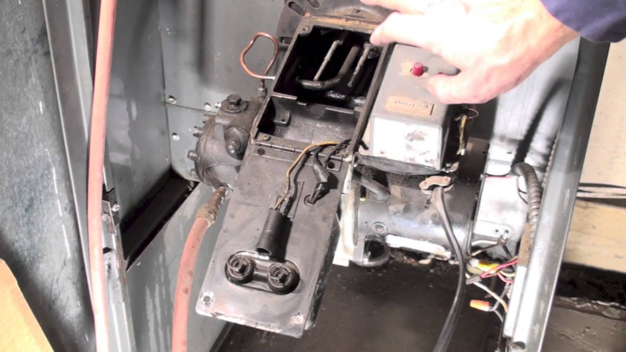
This video covers burner maintenance and service on a Beckett oil burner, including cad cell cleaning, burner nozzle replacement, electrode settings, burner.
BECKETT BECKETT OIL BURNERS Parts Model AG Sears PartsDirect
Beckett Burner Parts We have the beckett burner parts you need to get the job done right. Shop Beckett Burner Parts results (Showing 1 - 15) Sort By: Relevance. Grid List Rw Beckett.
Beckett Burner Parts Diagram Free Wiring Diagram
Ignitors & Burners Beckett Burners & Parts Beckett Burners & Parts Replacing or repairing a Beckett Burner has never been easier with this selection of Beckett Burners and Parts. Beckett Burners Air Tubes Replacement Heads & Static Disks Burner Motors Electrode Kits Blower Wheels Miscellaneous Parts Resources More About Beckett Burners & Parts
301 Moved Permanently
Follow these fi ve steps to properly adjust the burner: Step 1: Adjust the head/air until a trace of smoke is achieved. This can be accomplished by turn-ing the screw on the head/air adjustment plate assembly to increase air (CCW) or decrease air (CW). Step 2: At the trace of smoke level, measure the CO2 (or O2) .

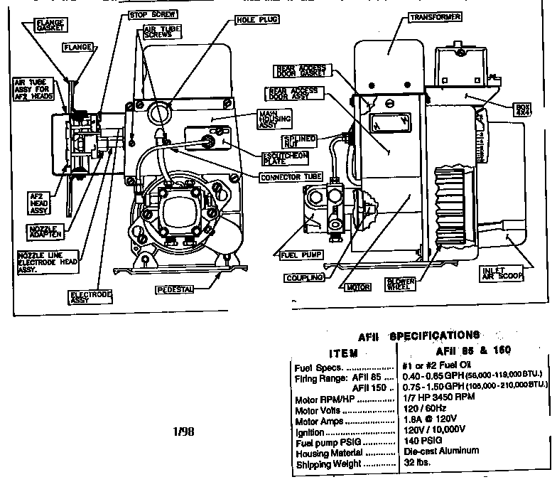
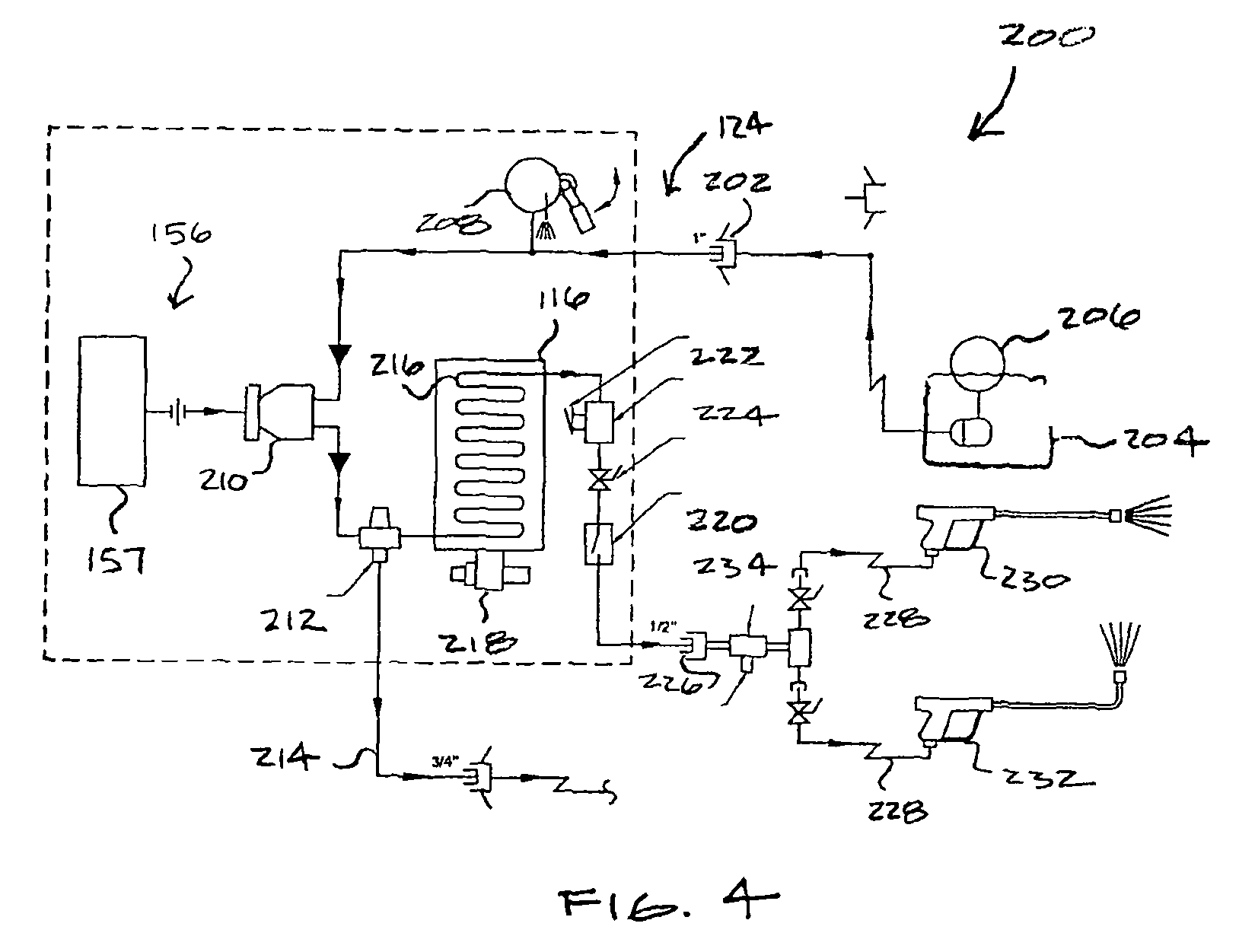
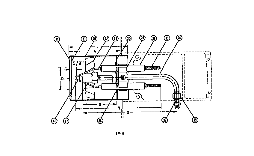
Schematic of a typical oil burner with labeled components. Download
Part No. Description. 51747. Air Boot Kit Includes: Burner air boot adapter, Vacuum Relief, Inlet air hood. 51851U. Outside air adapter for use with 5207301Uburner cover kit. 51908U. Air Boot Kit - Mobile Home Applications: Air boot, gaskets, instructions. AFII Residential Oil Burner.
Oil Burner Parts Diagram Hanenhuusholli
Burner Beckett AF Series Manual. (24 pages) Burner Beckett AF44XR Instruction Manual. Oil burner, f air tube combinations voltage 120 vac / 60 hz (12 pages) Burner Beckett 800 Instruction Manual. Beckett oil burner instruction manual cf500 cf 800 (16 pages) Burner Beckett BRYAN STEAM CF1000 Setup Manual.
